News
CNC Turret Punching: A Design Guide for Punched Sheet Metal Parts
September 23, 2026
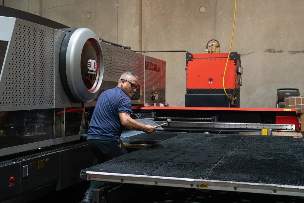
Most sheet metal parts are not defined by their outline. They are defined by what goes through them. Think of the mounting grid that locates a power supply, the vent field that keeps a cabinet cool, or the cable cutouts a technician threads a harness through. On a server chassis or a generator enclosure door, the perimeter is a rectangle. The value is in the features inside it.
That is the work CNC turret punching was built for. A turret punch press drives a hardened tool through sheet stock into a matching die. It shears out a slug in a single stroke, repositions, and does it again. Some machines run as fast as 1,350 strokes per minute. For a hole-dense part in production volume, punching is the most efficient, cost-effective way to add holes and formed features.
At Special Products & Mfg., Inc. (SPM), metal punching runs as its own department on the fabrication floor in Rockwall, Texas, alongside laser cutting and forming. This guide covers how the process works and what a turret can produce. It compares punching with laser cutting and stamping, lays out the design rules that keep parts out of rework, and explains what drives the cost of a punched part.
How Metal Punching Works
The shearing action
Metal punching is a shearing operation. The sheet sits between a punch and a matching die. The punch presses down into the die, and the material between them is sheared away as a slug. What remains is a hole in the shape of the tool.
The clearance between punch and die does most of the work. It is set as a percentage of material thickness, and it changes with the material and the gauge. According to The Fabricator, clearance that is too tight raises punching force and heat and promotes galling on the punch. Clearance that is too loose causes more rollover, rough edges, and large burrs. That is why the same nominal hole in 16-gauge cold-rolled steel and 16-gauge stainless does not use the same setup.
How a CNC turret press works
A traditional punch press runs one die set. A turret press carries a rotating tool magazine, the turret, loaded with dozens of punch-and-die pairs. Amada’s EMK M2 series, for example, uses a 58- or 55-station turret. CNC control positions the sheet under the ram on the X and Y axes, indexes the turret to the correct tool, and fires. Tool selection happens without an operator touching the machine.
Three consequences follow, and they explain most of punching’s advantages:
- No path to trace. A laser cuts a hole by tracing its outline. A punch makes the same hole in one stroke. On a dense grid of identical features, that adds up to a large throughput gap.
- One setup, many operations. A single program can punch mounting holes, nibble a custom cutout, form a countersink, lance a tab, and form louvers without the part leaving the machine.
- Auto-index stations. Auto-index stations rotate the tool itself. One obround or rectangular punch can then produce features at any angle, instead of needing a separate tool for each orientation.
SPM’s punching department runs automated turrets built for complex, high-feature parts. Because the process is CNC-driven, the same program produces the same part run after run. For an OEM buying the same bracket every month, that consistency matters more than peak speed on any single sheet.
Features a Turret Press Can Produce
Hole punching is the headline, but a well-tooled turret does more. SPM’s machines produce holes, countersinks, embossments, louvers, and other formed features, plus intricate hole patterns and nibbled custom shapes.
| Feature | What it is | Why it matters |
|---|---|---|
| Piercing and hole patterns | Round, square, obround, rectangular, and special-shape holes | Fastener, hardware, connector, and cable entry locations in one program |
| Cluster tooling and perforating | One punch carrying many tips | 2 to 120+ tips per punch put repeat patterns and vent fields down in fewer hits |
| Nibbling | Small, overlapping hits along a programmed path | Custom contours with no custom tooling; the tradeoff is a scalloped edge and more hits |
| Countersinks | Formed seats for flat-head fasteners | Produced in cycle instead of as a secondary machining step |
| Embossments and dimples | Raised or recessed formed features | Formed on the turret before the part moves to the press brake |
| Louvers | Formed airflow openings | A punch forms them natively; a laser cannot |
| Lancing | A partial cut that leaves material attached | Tabs and similar features without a separate operation |
| Extruded holes | Drawn collars around a hole | Thin material needs an extrusion to give a tapped screw enough thread to engage |
| Notching, corner relief, and marking | Material removed at edges and corners; marked characters | Parts form cleanly at the press brake and carry traceability marks |
No single feature here is exotic. The value is that all of them happen in one setup, on one machine, before the part moves to forming. Every operation folded into the punching cycle removes a setup, a handling step, and a queue downstream.
Punching vs. Laser Cutting: How to Choose
The answer depends on feature density, contour complexity, and volume. SPM runs both processes under the same roof, so process selection is an engineering decision rather than a sales one. A shop with only lasers has to quote a louvered panel as a laser job plus a secondary forming operation. A shop with both can tell you which route is actually cheaper.
Where punching wins
- The part carries many repeated features, such as mounting grids, vent fields, perforation, and cable entries.
- The design uses standard hole sizes that map to existing tooling.
- Formed features are required. Louvers, embossments, countersinks, extrusions, and lances are punching-only.
- Volumes are medium to high and the part repeats, so programming and tooling costs spread across the run.
Where laser cutting wins
- The part is dominated by intricate outside contours or curves rather than holes.
- Geometry changes often, or the job is a prototype. A fiber laser cuts nearly any contour without a tool change.
- Nesting efficiency is critical. Laser nesting typically fits more parts on a sheet, while punching needs clamp zones and a skeleton to hold the sheet.
The comparison at a glance
| Factor | CNC Turret Punching | Fiber Laser Cutting |
|---|---|---|
| Best-fit geometry | Hole-dense parts, repeating patterns, perforation | Complex contours, curves, variable profiles |
| Formed features | Yes — louvers, embossments, countersinks, extrusions | No — requires secondary operations |
| Tooling | Standard turret library; custom dies for special profiles | None |
| Design changes | May require tooling or program rework | Minimal — revise the file and cut |
| Material utilization | Good; needs clamp zones and skeleton | Typically better via tight nesting |
| Edge condition | Sheared edge with burr; deburr as required | Clean cut edge with precise holes |
| Ideal volume | Medium to high, repeating production | Prototype through medium; any volume with complex contours |
In practice, many parts use both. A common approach runs the outer profile on the laser and the hole and form content on the turret. Another option is a punch/laser combination machine that does both in one automated cell. SPM’s engineering team reviews every RFQ for fit, so the process split is worked out during quoting rather than left to the print.
Punching vs. Stamping
The two terms get used interchangeably, but they are different processes. Stamping is an umbrella term for forming operations such as bending, embossing, flanging, and coining, usually run on a dedicated die. Punching removes material to create holes and cutouts.
| Factor | CNC Turret Punching | Stamping |
|---|---|---|
| What it does | Holes, cutouts, and formed features in a flat sheet | Shapes a blank through multiple forming operations |
| Tooling | Shared library of standard punches and dies | Purpose-built die for each part |
| New-part cost | Programming time; little or no new tooling | Higher upfront die investment and longer lead time |
| Best-fit volume | Low to medium-high, repeating production | Very high volume, where die cost spreads across the run |
For OEMs running thousands of parts a year rather than hundreds of thousands, punching is usually the better economics.
Materials, Thickness, and Tolerances
SPM punches aluminum, steel, and stainless steel as standard, with specialty alloys available on request. Across its fabrication floor, SPM works material from 0.020″ to 0.500″ thick, depending on the material. Standard tolerance is ±0.005″, with tighter values available on request. SPM doesn’t publish separate punching limits; they depend on the feature, material, and tooling, and SPM confirms them against your print during quoting.
How material changes the punching setup
Material matters more in punching than in laser cutting, because punching is mechanical. Mate Precision Technologies publishes tooling guidelines for both the smallest practical hole and the die clearance for each material:
| Material | Minimum hole diameter (standard tooling) | Minimum hole diameter (fully guided tooling) | Total die clearance |
|---|---|---|---|
| Aluminum | 0.75 × material thickness | 0.5 × material thickness | 15%–25% of thickness, rising with gauge |
| Mild steel | 1 × material thickness | 0.75 × material thickness | 20%–30% of thickness, rising with gauge |
| Stainless steel | 2 × material thickness | 1 × material thickness | 20%–35% of thickness, rising with gauge |
Design guidelines on this page are general industry starting points, not specifications or guaranteed limits for any individual part. Actual minimums, clearances, and tolerances depend on material, thickness, tooling, and part geometry. Confirm requirements for your part against your drawing with SPM’s engineering team during quoting.
Source: Mate Punching & Forming Guide. Stainless also takes more force to punch, because its shear strength is higher than mild steel’s. Galvanized and pre-painted stock can wear the punch surface or cause galling, which is where punch coatings and lubrication come in.
Edge quality and burrs
A sheared edge has four distinct zones. Rollover forms where the tool first contacts the sheet. Below it sit a smooth burnished band and a rougher fracture zone, and a burr forms on the trailing edge of the cut. The burr is a normal product of the process. It still matters, because burrs and sharp edges can cause problems in packaging, handling, and assembly, and can be a safety hazard.
Call out edge condition on the print where it matters. A note such as “break all sharp edges” or a maximum burr allowance tells the shop what you need. Otherwise it gets discovered at incoming inspection. Specify burr direction where one face is a sealing or mating surface.
Design for Manufacturability: Rules That Govern Punched Parts
Most punching problems are designed in, not manufactured in. The rules below are published industry starting points, not SPM-specific limits, which vary by tooling and material. SPM’s planners and programmers review new parts for problem points and offer DFM solutions before production.
DFM quick reference
| Design rule | Common guideline (T = thickness, R = inside bend radius) | Published by |
|---|---|---|
| Minimum hole diameter | 1 × T in mild steel; 2 × T in stainless; smaller in aluminum or with fully guided tooling | Mate, DFMPro |
| Hole edge to part edge | About 1.5 × T | Five Flute |
| Hole edge to bend | 2.5T + R is common; published values range from about 1.5T + R to 3T + R | Five Flute |
| Slot width | Wider than T | Five Flute |
| Notch width | At least 1.5 × T | DFMPro |
| Extruded hole to part edge | At least 3 × T | DFMPro |
| Between extruded holes | At least 6 × T | DFMPro |
Design guidelines on this page are general industry starting points, not specifications or guaranteed limits for any individual part. Actual minimums, clearances, and tolerances depend on material, thickness, tooling, and part geometry. Confirm requirements for your part against your drawing with SPM’s engineering team during quoting.
Why the minimum hole rule exists
Very small holes put small punches at risk of breaking. SOLIDWORKS DFMXpress checks the ratio of hole diameter to sheet thickness for this reason. The safe ratio climbs with material strength. That is why stainless needs a larger hole than mild steel, while aluminum and fully guided tooling can go smaller.
Why edge and bend distances matter
A hole placed too close to a part edge can distort the edge. A hole too close to a bend distorts during forming, and the safe distance grows with both thickness and bend radius. Where a feature must sit near a bend, adding a relief cut usually beats fighting the geometry.
Why formed features need more room
Formed features need more space than plain holes. Mate notes that extrusions can deform when placed too close to sheet edges, punched holes, or other forms. Louvers, embossments, and lances also change the sheet locally, so plan hole locations around them.
Standardize on tool-friendly sizes
This is the highest-leverage change most designers can make. A part that reuses a handful of standard hole diameters punches faster and cheaper than one with fourteen unique sizes. The turret can hold every needed tool at once and never waits on a manual change. When parts in a family share the same hole sizes, the savings extend across the whole program.
One related warning: a part may start as a low-volume laser job and later move to a turret for production. If so, design to the punching rules from the beginning. A feature that is easy to cut on a laser but awkward to punch becomes a redesign at exactly the moment the program ramps.
Punching at SPM: One Roof, One Supplier
Automation and Lights Out Manufacturing
Throughput on a punch press is not only about hits per minute. It also depends on how many hours the machine runs unattended. All of SPM’s metal punching machines and punch/laser combination machines have loading towers with multiple shelves of material and sheets. That lets the punching line run extended Lights Out Manufacturing, which lowers costs and lead times.
What happens after the punch
A punched flat blank is rarely the deliverable. It becomes a formed bracket, a welded frame, a coated door, or a populated enclosure. Every handoff between suppliers adds freight, lead time, inspection, and someone to argue with when a dimension is wrong.
SPM runs punching, laser cutting, and forming side by side on one fabrication floor. CNC machining, welding (MIG, TIG, robotic, spot, and stud), powder coating, and electro-mechanical assembly run in the same operation. A punched panel can be formed on ATC press brakes and welded into an assembly. It can then go through six-stage pre-treatment and powder coat, be populated with hardware and passive components, and be tested, packaged, and shipped.
The SPM Complexity Model
SPM frames this work with its Complexity Model, a five-level framework:
- Level 1: single-piece mechanical components
- Level 2: cosmetic-grade finishes
- Levels 3 and 4: mechanical and complex mechanical assemblies
- Level 5: fully populated electro-mechanical assemblies with testing and logistics
Sheet metal fabrication is foundational at every level. The same turret produces the Level 1 bracket and the panel inside a Level 5 cabinet. SPM’s value-added services support all five levels. They include New Product Introduction, DFM support, inventory management, supply chain management, transportation, and logistics. Rapid prototyping is also available to a trusted selection of customers.
Industries SPM’s punched parts serve
Punched sheet metal ends up wherever equipment needs ventilation, mounting, cable management, or a panel that fits precisely against something else:
- Cloud & Data Storage: hyperscale server racks, data center cabinets, and networking chassis with perforated airflow panels
- Industrial Automation: conveyor chassis and guarding, cobot enclosures, robot bases, and integrator cell components
- Electrical & Electronics: NEMA enclosures and panels populated with passive devices in-house
- Oil, Gas & Energy: control panels, rugged field enclosures, and skid frames
- HVAC & Commercial: cabinets, plenums, and chassis for commercial HVAC equipment
- Power Generation & Utilities: weather-rated generator enclosures and switchgear cabinets
- Medical & Healthcare: equipment cabinets, mobile carts, and rack systems
- Test Systems, Transportation, and Consumer & Retail Products: test fixtures and frames, fleet and rail fabrications, fuel dispenser housings, and store fixtures
Quality, certification, and track record
SPM is ISO 9001 certified company-wide. Its ERP system, in place since 2015, supports traceability, quality tracking, and operational visibility. Lean Manufacturing and Continuous Improvement are daily practice on the floor. The quality department uses InspecVision 3D optical inspection on complex parts and assemblies.
SPM was named the 2025 Fabricator of the Year by The Fabricator magazine and the Fabricators & Manufacturers Association (FMA). It has also appeared on The Fabricator’s FAB 40 list multiple times. SPM has been manufacturing since 1963 and reports 99.6% on-time delivery. It has 200+ team members and three Texas facilities totaling 182,000 square feet: a 145,000 sq ft headquarters in Rockwall, plus Fate and Round Rock.
What Drives the Cost of a Punched Part
These are the levers that move a punching quote:
- Feature count and density. More hits mean more cycle time. But punching’s cost advantage over laser grows as feature density climbs.
- Hole size variety. Standardizing sizes reduces tool changes and program time.
- Material and gauge. Thickness and hardness drive tonnage, tool wear, and burr condition.
- Nesting efficiency. Geometry determines how many pieces come off a sheet and how much becomes skeleton.
- Secondary operations. Deburring, hardware insertion, forming, welding, and finishing each add steps. There are far fewer handoffs when they happen in one building.
- Volume, tolerance, and cosmetic callouts. Setup cost spreads across the run. Tighter-than-standard tolerances and Class A surfaces are achievable, but specify them only where they are needed.
Getting a Metal Punching Quote from SPM
Send your specs: drawings or 3D models, material and gauge, finish requirements, annual volume, and target timing. SPM responds within one business day. If a feature on your print is going to fight the process, you will hear about it during quoting rather than after the first article. SPM’s DFM support and its customer education program, SPM University, exist for that conversation.
SPM serves OEMs that need repeat production of sheet metal components, enclosures, cabinets, weldments, and assemblies, from prototype through steady production. For those programs, the punching department is one part of an integrated supplier rather than a standalone service.
Frequently Asked Questions About CNC Turret Punching
What is the difference between punching and laser cutting?
Punching shears material mechanically with a punch and die, one stroke per feature. Laser cutting traces a contour with a focused beam. Punching wins on hole-dense parts, repeating patterns, and formed features. Laser cutting wins on intricate outer contours, frequent design changes, and prototypes. Many parts use both processes, and SPM runs both under one roof so the split can be decided on engineering merit.
When should a part be nibbled instead of punched with a dedicated die?
Nibbling uses a series of small, overlapping punch hits along a programmed path. It produces a contour no dedicated die exists for, so custom shapes carry no custom tooling cost. The tradeoff is a scalloped edge and more hits. Where a specific profile will repeat at volume, a dedicated tool gives a cleaner edge and a faster cycle.
What is the smallest hole that can be punched?
The general guideline is a hole diameter at least equal to material thickness in mild steel. Mate’s tooling guidelines put the minimum at about 0.75 times thickness in aluminum and 2 times thickness in stainless with standard tooling, and fully guided tooling can go smaller. SPM confirms specific minimums against your material, gauge, and print during quoting.
Design guidelines on this page are general industry starting points, not specifications or guaranteed limits for any individual part. Actual minimums, clearances, and tolerances depend on material, thickness, tooling, and part geometry. Confirm requirements for your part against your drawing with SPM’s engineering team during quoting.
How far should a hole be from an edge or a bend?
A common guideline is about 1.5 times material thickness between a hole edge and the part edge. For bends, 2.5T + R is a common guideline, where T is material thickness and R is the inside bend radius; published values range from about 1.5T + R to 3T + R. Holes placed closer than that can distort at the edge or during forming.
Design guidelines on this page are general industry starting points, not specifications or guaranteed limits for any individual part. Actual minimums, clearances, and tolerances depend on material, thickness, tooling, and part geometry. Confirm requirements for your part against your drawing with SPM’s engineering team during quoting.
Disclaimers
Design guidelines on this page are general industry starting points, not specifications or guaranteed limits for any individual part. Actual minimums, clearances, and tolerances depend on material, thickness, tooling, and part geometry. Confirm requirements for your part against your drawing with SPM’s engineering team during quoting.
Have a project to quote?
Send us your specs. We’ll respond within one business day.